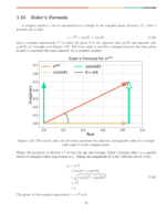
Normalizing a filter to unit gain at some frequency  is as simple as dividing the filter weights by the magnitude of the discrete-time Fourier transform (DTFT) at
(1) ![\begin{equation*}h_{norm}[n] = \frac{h[n]}{\left|\sum_{k} h[k]e^{-j\omega_g k}\right|}\end{equation*}](https://www.wavewalkerdsp.com/wp-content/ql-cache/quicklatex.com-ba872b1a24b25a7636baf83f65367856_l3.png "Rendered by QuickLaTeX.com")
where ![h_{norm}[n]](https://www.wavewalkerdsp.com/wp-content/ql-cache/quicklatex.com-f15e723d390fed1b677acbfad6c17ada_l3.png "Rendered by QuickLaTeX.com") is the normalized filter and h[n] is the unnormalized filter. To see why this is the case, start by taking the DTFT of h[k] which is
is the normalized filter and h[n] is the unnormalized filter. To see why this is the case, start by taking the DTFT of h[k] which is
(2) ![\begin{equation*}H\left(e^{j\omega}\right) = \sum_{k} h[k]e^{-j\omega k}.\end{equation*}](https://www.wavewalkerdsp.com/wp-content/ql-cache/quicklatex.com-9cf3fa91f0e05547f7b379f187f9d32f_l3.png "Rendered by QuickLaTeX.com")
The unnormalized filter gain at is the magnitude of the frequency response
(3) ![\begin{equation*}\left| H\left( e^{j\omega} \right) \right|_{\omega = \omega_g} = \left| \sum_{k} h[k]e^{-j \omega_g k} \right|\end{split}\end{equation*}](https://www.wavewalkerdsp.com/wp-content/ql-cache/quicklatex.com-b06e845da67dbf73e219fa6f1915954d_l3.png "Rendered by QuickLaTeX.com")
A filter gain of 1 at is achieved by scaling the frequency response (2) by the unnormalized filter gain at (3). The frequency response of the normalized filter is therefore
(4) ![\begin{equation*}\begin{split}H_{norm} \left( e^{j\omega} \right) & = \frac{ H \left( e^{j\omega} \right) }{ \left| H \left( e^{j\omega} \right) \right|_{\omega=\omega_g} } \\& = \frac{ H \left( e^{j\omega} \right) } { \left| \sum_{k} h[k] e^{-j\omega_g k} \right| }.\end{split}\end{equation*}](https://www.wavewalkerdsp.com/wp-content/ql-cache/quicklatex.com-dc53d1931d0030ea9b93472c1cc4f208_l3.png "Rendered by QuickLaTeX.com")
The time-domain filter weights are the inverse DTFT of (4)
(5) ![\begin{equation*}\mathcal{F}^{-1} \left\{ H_{norm} \left( e^{j\omega} \right) \right\} = \frac{ \mathcal{F}^{-1} \left\{ H \left( e^{j\omega} \right) \right\} }{ \left| \sum_{k} h[k]e^{-j\omega_g k} \right| }\end{equation*}](https://www.wavewalkerdsp.com/wp-content/ql-cache/quicklatex.com-360e3abc17832dafaee477012daa9275_l3.png "Rendered by QuickLaTeX.com")
which is the same as (1)
(6) ![\begin{equation*}h_{norm}[n] = \frac{ h[n] }{ \left| \sum_{k} h[k]e^{-j\omega_g k} \right| }.\end{equation*}](https://www.wavewalkerdsp.com/wp-content/ql-cache/quicklatex.com-e545481c2691142e48a947f4bdf90ba1_l3.png "Rendered by QuickLaTeX.com")

 are related through

![h_{g}[n]](https://www.wavewalkerdsp.com/wp-content/ql-cache/quicklatex.com-a76e773daf157ff3ea842fae5549ec05_l3.png "Rendered by QuickLaTeX.com") are therefore
are therefore![\begin{equation*}\begin{split}h_{g}[n] & = G \cdot h_{norm}[n] \\& = \frac{G \cdot h[n]}{\left| \sum_{k} h[k]e^{-j\omega_{g} k} \right| }.\end{split}\end{equation*}](https://www.wavewalkerdsp.com/wp-content/ql-cache/quicklatex.com-c5159419218270c204b783fac91bdf58_l3.png "Rendered by QuickLaTeX.com")
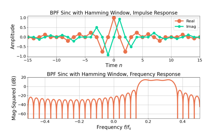
Figure 1 gives the impulse and frequency responses for an unnormalized sinc with 31 filter weights with a Hamming window applied. Figure 2 gives the responses after the filter is normalized to 0 dB gain at  using (6) and Figure 3 gives the responses after scaling the same filter to have a gain of 6 dB at using (10).
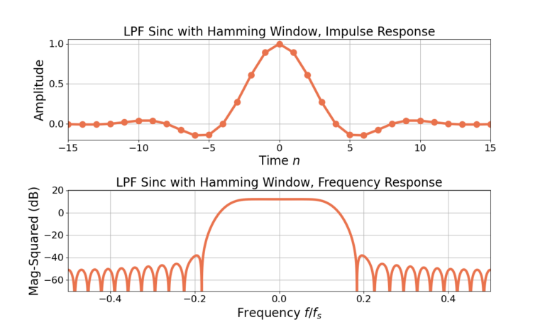
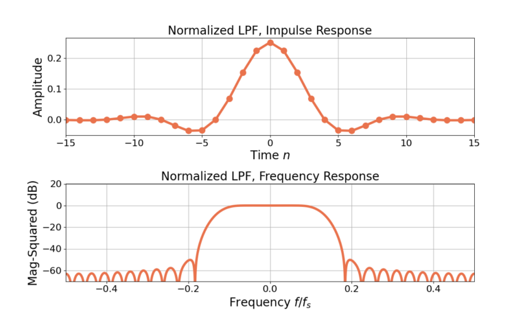
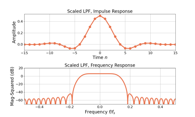
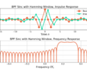
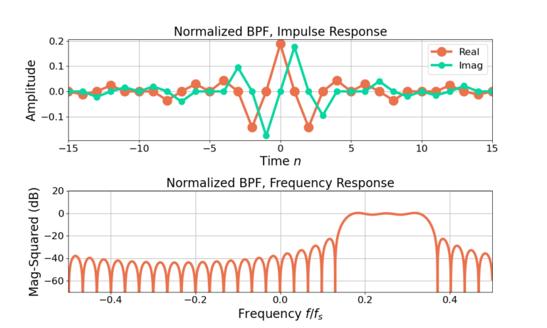
Figure 4 gives the impulse and frequency responses for an unnormalized sinc with 31 filter weights with a Hamming window applied and then frequency shifted to band-pass. Figure 5 gives the responses after the filter is normalized to 0 dB gain at  , which is equivalent to
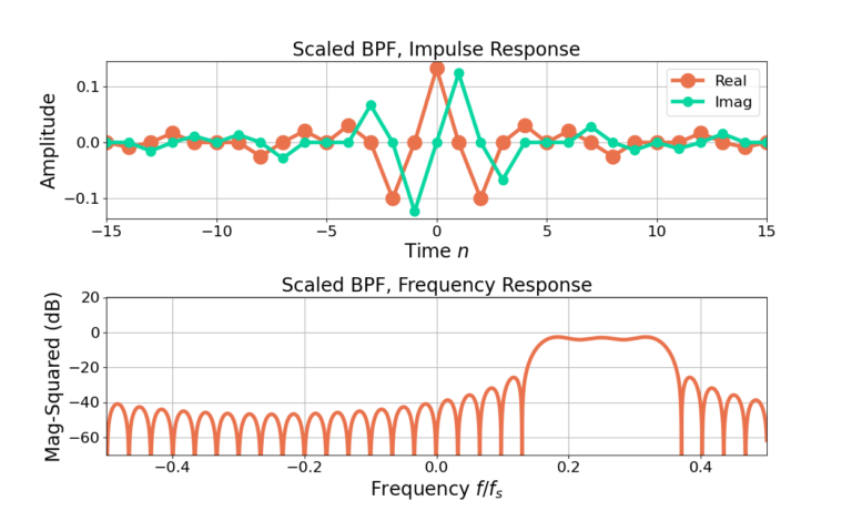
  , using (6) and Figure 6 gives the responses after scaling the same filter to have a gain of -3 dB using(10).
The gain of an FIR filter can be designed by first normalizing the weights to unit gain at frequency and then scaling each of the weights by the desired linear gain. The filter normalization is calculated by diving the filter weights by the magnitude of the frequency response at .
More blogs on filter design: