

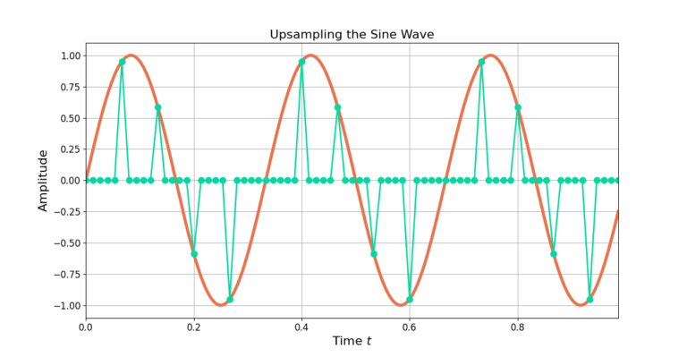
Low pass filtering is needed to smooth the zero-padded signal to fill in the gaps between the non-zero samples. A low pass filter is designed with a cut-off frequency of
(1) 
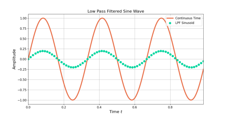
where  is the sampling rate and M is the interpolation factor [oppenheim1999, p.173]. Figure 3 shows the result after low pass filtering with a Remez-designed filter from this blog post with a normalized cutoff frequency of
  where M=5.
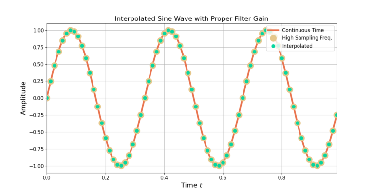
Interpolation is a two step process: upsampling and low pass filtering. The LPF must have a cutoff frequency of  and a gain of M when interpolating by a factor of M.
More DSP blogs!
4 Responses
Thank you–this was just what I needed! Such a clear, simple explanation!
Wouldn’t upsampling also require a PLL?
Good question. Interpolation by itself does not require a PLL (phase locked loop). Interpolation is the process of increasing the number of samples used to represent a discrete-time signal; increasing the sample density in a sense. In the frequency domain this changes the proportion of the available bandwidth the signal occupies. The larger the interpolation rate the smaller the ratio of the signal’s bandwidth to the sampling rate. Within the RF world a PLL is used to track (or synchronize to) a signal’s carrier frequency and/or phase. These two operations, interpolation and PLL, are disjoint from one another and can be applied independent of one another. I hope this helps. Please let me know if you have any more questions.
Linear interpolation inside the convex hull, extrapolation outside it: https://sciencelimelight.blogspot.com/2025/08/the-convex-hull-for-neural-networks.html